Applies to
DECADE Elite, ROXY Exceed
Summary
Test for control board TTL input trigger. In case of triggering issues to see if hardware or software is not working.
Test 1 – Export settings, check parameter 5C
The pin status can be assigned to different actions in the DECADE Elite ECD. For example, an autozero input at pin 18 can be assigned to board 1 or ALL boards. The assignment parameter is “1” or “A”, this is all good. However, when the assignment is “0” for some reason, nothing will happen and it seems a malfunction. To check this, connect the device with DECADE Dialogue. Go to File/Export settings and open the text file in notepad or any other text editor. Check the parameter 5C is valid, not holding zero’s. If 5C is holding “0” or empty, create a new file in Notepad with the line:
” 1111 5C connector IO input mask for command #46″
and select File/Import settings. Use exactly the same 6 empty spaces to start the line, and the 8 empty spaces after 1111. Do not use a “+” in front of the number! Repeat the export and check all is good.
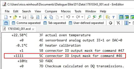
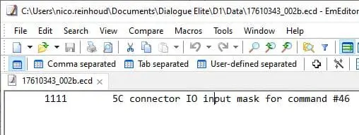
Fig. 1. On the left, the correct 5C parameter in the export file, on the right the import file created for “File/Import settings” in case the 5C needs correction. Repeat export/import until the correct answer is in the export!
Test 2 – IO test in service mode
In the service mode of the DECADE Elite / ROXY Exceed, go to TEST, IO, IN. The display shows the status of all inputs. To test the screen is correct, open/close the door and the “DS” status will go from “0” to “1” to “0”. Switch on the unit. Connect the IO cable with connector board to the rear panel of the ECD and with a wire or paper clip make a short with the pin and ground. The value in the display should go from “0” to “1”. See below example, where pin 21 is shorted with pin 25 (ground). When the result of grounding the pin is not “1” (the status “0” does not change) it points at a hardware failure. Double check with other pins as well. Below photo is from an open unit at Antec’s test lab. For this test in the field it is not needed to open/disassemble the unit!
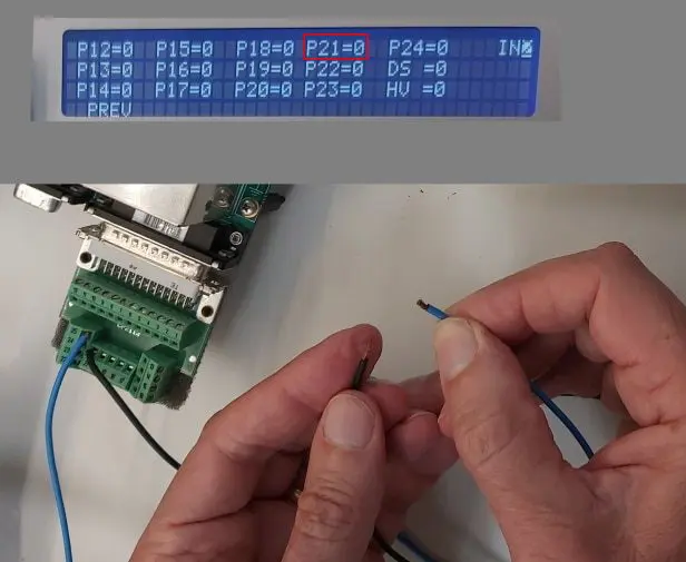
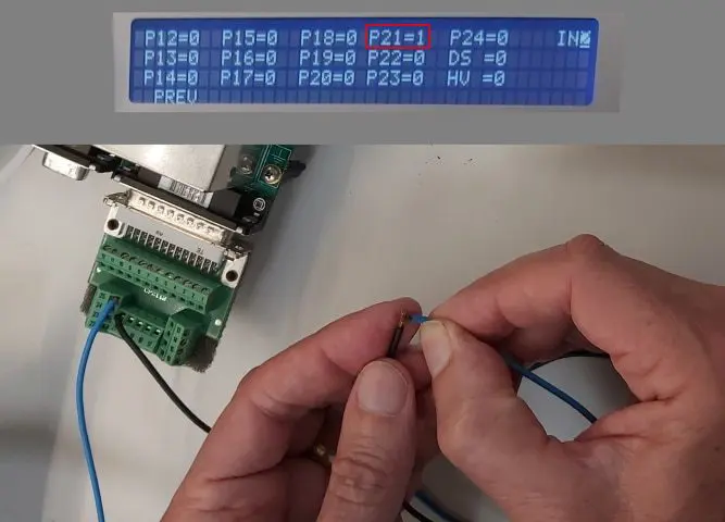
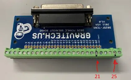
Note that Antec’s IO board pin 25 is the second from the right, the supplied board has 26 pins in total! In case of a DECADE LITE this test is only possible when connecting a display module (available from Antec).
Recent Comments