Gas bubbles in flow cell
Applies to
Electrochemical detector
Summary
Proper and continuous degassing is necessary in LC-EC, one time degassing using ultrasonic treatment is usually not enough.
Cause and remedy
Gas bubbles in the flow cell are caused by:
- Under-pressure in the cell because the outlet is below the flow cell level. Raise the waste bottle level to about the same level as the cell. Not putting it on the floor below the working desk.
- Improperly degassing of mobile phase. Apply a high efficiency inline degasser.
- High temperature in working compartment changes the solvability of gas in mobile phase especially in water-MeOH mixtures. Apply a little back pressure after the cell if needed.
- Carefully check the smoothness of the tubing entering the flow cell. A rough cut might cause air but at least noise. Cut a sharp smooth edge if needed.
- The inlet hole of the flow cell is not smooth or there are particles in that part. This can be checked visually with a magnifying glass. Cleaning can be done by flushing with water. Clean out the inlet hole, remove particles or plastic residue in the thread.
- Over potential, or injection of air. Optimize method, or apply a little back pressure after the cell.
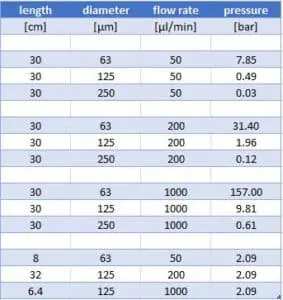
In case a little back pressure after the cell is needed, apply a piece of narrow bore tubing after the cell. This will create some back pressure and avoid gas formation. This should be optimized depending on the flow rate, too much pressure will cause a leak, typically apply between 1 and 2 bar. Use the Antec Calculator for pressure vs flow rate and diameter (see table below).
Flow rate, diameter and pressure calculations for PEEK tubing:

*Note that the PEEK tubing diameter is not very exact, and deviations from the calculated pressure may occur. Flow rate and length are linearly related to pressure (compare the 2nd and 3rd in table). The pressure relates to diameter to the 4th power. A 2 times larger tubing results in 2^4 (16 times) smaller back pressure.