Applies to
Electrochemical detector
Summary
The noise level is much higher than expected.
Cause
Studying the noise trace can be helpful to find the source of noise.
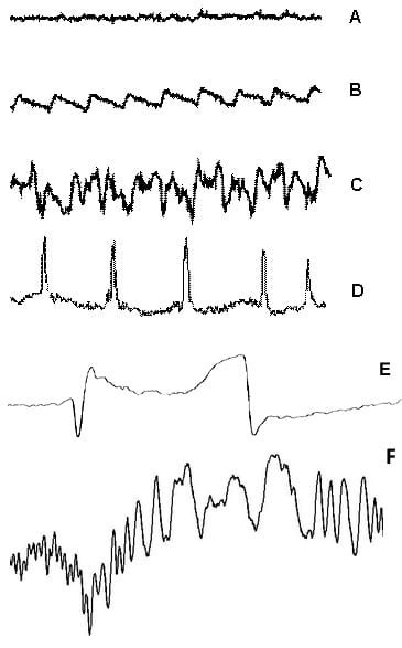
Fig. 1. Examples of noise.
| Type of noise | Comment | |
| A | ‘normal’ random noise | no problem, for comparison only |
| B | not random, regular pattern | Pump pulsations, disappears if the pump is ‘off’. Look for equipment with the same frequency |
| C | random, but 10 times ‘normal’ (A) | Air bubbles in cell, high background current, maintenance |
| D | not random, spike pattern | insufficient degassing of mobile phase |
| E | drifting, with jumps in baseline | flow cell, reference electrode, cell cable |
| F | oscillations with shifting frequency and amplitude | static electrical charge build-up in the system |
Diagnosis
In all cases of excessive noise a 3-step procedure helps to locate the source:
Dummy cell test (read more…) – in case failed, it points at ECD electronics or wiring to PC as source of noise. In case passed the problem is not related to ECD electronics >> continue with stop flow test
Stop flow test (read more…) – in case stopping the flow shows a significant decrease of noise and/or background current, the problem is HPLC related. An issue with mobile phase, tubing, pump, pulse damper, autosampler, column, bubbles, or some contamination most likely. In case stopping the flow does not change the noise level much indicates that the source of the problem is not related to the HPLC system >> continue with flow cell contact test
Flow cell contact test (read more…) – in case this test is failed apply service or replace the flow cell. This test is not for a FlexCell.
Noise sources
| Source of noise | Remedy | Type | |
| 1 | malfunctioning HPLC pump or other LC component (i.e. pulse dampener). | Servicing of the pump and periodic maintenance avoids most problems. Check the HPLC plumbing on a regular basis and avoid leaking. Use of a pulse dampener is required. | B |
| 2 | lab equipment such as air co, heater, in-line light source, mixer, refrigerator etc | Other equipment must not be used if interfering with the analysis. Sometimes proper grounding or using another wall socket helps. For grounding instructions see dedicated kb paper. | B. F |
| 3 | dripping of mobile phase in waste bottle or from a leak | Keep the outlet tubing under the liquid level to avoid dripping. | B, D |
| 4 | gas bubble in flow cell or REF compartment. | Always install the flow cell with outlet on top to ensure self clearing of bubbles, use an in-line degasser. One time degassing (ultrasonic bath) is not good enough! | B |
| 5 | rough cut at inlet tubing or indented tubing caused by over tightening of finger tight | Inlet tubing at flow cell: install another piece of square cut tubing, preferably PEEK. Use a professional tubing cutter in hte correct way. | C |
| 6 | contamination in mobile phase, is observed together with abnormal increase in background current. | Contamination in mobile phase: prepare a fresh mobile phase, clean the cell before continuing and do not recycle. | C |
| 7 | high cell potential | if this high potential is necessary, not much can be done. Advice: optimize working potential and data filtering for best signal-to-noise ratio. | C |
| 8 | internal leakage in flow cell | Internal contact between AUX-WE (can be checked with flow cell contact test). Contact supplier to arrange repair | C |
| 9 | poorly functioning Faraday shield, oven is open, grounding not sufficient | Always close the oven door to have a functional Faraday shield. Make sure the grounding circuitry in the lab is sufficient. Waste line should not be unnecessarily long as it can pick up noise sources as an antenna. Grounding: apply additional grounding cables to see if noise disappears (see KB paper on grounding). | C, F |
| 10 | problem with data acquisition, unshielded data cable. | Data acquisition: compare peak-to-peak noise with readout in display of the detector, disconnect data cable from the detector to see if this is an ‘antenna’ to pick up environmental noise. If so, replace data cable and connections. | C, F |
| 11 | no conduction in mobile phase (no ions) | No conduction: mobile phase should contain at least 10 mmol/L of ions (between 10 – 200 mM). | C |
| 12 | WE exposed to extremely high potential | Exposure to high potential: the working electrode has been suffering from a very high potential. The color of glassy carbon electrode turns blue and lacks mirror like finish. Contact supplier. | C |
| 13 | electric discharges. Often due to improper grounding near the flow cell. | Never apply metal tubing to close to the cell. Use PEEK instead. Put a metal low dead volume connector in the flow cell outlet PEEK tubing at about 4″ (10 cm) after the outlet. Connect the metal to a wire connected to detector ground (rear panel) | D |
| 14 | gas bubbles in the mobile phase, poor degassing, or released by column | Always install the flow cell with outlet on top to ensure self clearing of bubbles, use an in-line degasser. One time degassing (ultrasonic or filtration) is not good enough! | D |
| 15 | poor contact with cell cable or internal break in cell cable | Check contacts and cable with voltmeter, inspect cable for corrosion. Replace cell cable in case of any doubt. | E |
| 16 | malfunctioning of reference electrode | Replace a salt bridge REF, or apply maintenance. See flow cell manual for details. | E |
| 17 | negative pressure drop after flow cell | The outlet tubing after the flow cell should lead to a higher level which results in a little positive back pressure. Simply keep waste/solvent bottle above (not below) the flow cell level. | D |
| Other causes |
Recent Comments